Longtime readers of our blog will know that one (or two?) of the earliest
projects we shared in a previous blog post are passports
and door-opener. If you’ve missed it, you should definitely go and check out
how they work, but today we’ll be focusing on door-opener.
We spent the past year designing, building, and deploying the new door-opener
that would solve some of the problems that started to manifest with the
original, while adding new quality-of-life improvements for the organizers
setting up Hack Night.
I shared parts of how door-opener-v2 came together
during my BENTO talk, but because the goal of BENTO was to
condense everything down to within 15 minutes, a lot of material was left on
the cutting room floor. So here’s a more detailed look at how door-opener-v2
came together, starting all the way back at the beginning.
Entropy, and the cruel passage of time
door-opener was initially built by Hazel Roeder, and her design had been
working flawlessly, up until Fall 2025. Unfortunately, while the design itself
would’ve lasted a lot longer, the materials for the suction cups, as well as
some of the internal components like the fan bearings, were starting to wear out.
We decided to prioritize a more permanent solution for this problem when people reported that they couldn’t get to Hack Night anymore, because the modules kept losing their grip and falling off of the surfaces.
So on September 2025, a new channel on our Discord was created, and I’ll try my best to summarize the important milestones we hit up to the present.
Idea-sharing and trimming
We first had to decide what the second revision of the project would do better compared to the first one. Some of the ideas proposed were:
- Add a slideshow for cycling through different pages on
door-opener - Add self-diagnosing capabilities in case
door-openeris set up incorrectly for Hack Night - Make the servo portion of
door-openerindependent - Figure out a new attachment style for the servo
- New enclosure design
- A camera intercom system so that organizers can see who is at the door
- Integrating with
phone-bell(we’ll get to that, too) - Attendance system for tracking people coming to Hack Night
- Remote opening and control of
door-opener
Most of the ideas did eventually make it to the final product, but we haven’t even gotten to the first prototype yet. For that, we needed to order some parts.
After looking through the potential ideas and features list, we decided that a
new enclosure for door-opener would be needed after all, and a parts list that
looked suspiciously similar to the first revision was ordered, with the addition
of a camera. Since we were redesigning the enclosure anyway, we also decided
to use a different part for the screen, which did complicate the design and
build process quite a bit. (More on that later.)
Branching off a sub-project
While we worked on the new revision for door-opener, we also focused on the
idea where the servo that sat on top of the ADA button would be made more
independent compared to how it was before. Previously, an organizer had to run a
microUSB cable between the servo module and door-opener, and depending on how
it was plugged in, the servo would fail to be initialized and require a power
cycle on the Pi’s side. Unfortunately, this wasn’t immediately apparent to the
organizer setting things up, and because they had several other tasks to
complete in order to get Hack Night ready, attendees would often show up to a
door-opener that wouldn’t actually open the door.
So the spin-off project got the name ada-pusher, and we took the opportunity
to swap out the servo with a linear actuator for better reliabilty. For the
connection back to door-opener, we decided to use Bluetooth Low Energy, or
BLE for short. Wi-Fi was briefly considered but was decided against because it
might become a security risk for Bechtel, the building that we were hosting
Hack Night at.
Updating the codebase
While waiting for the hardware parts to arrive, I also started work on updating the repository and the dependencies required. For example, the repository in the beginning did not compile successfully on Windows, until the NFC library was updated to properly work with CMake. Since the repository hadn’t been worked on since Hazel graduated, I focused mostly on making sure the dependencies were up-to-date.
Any visual changes would have to wait until the new prototype was built, but by
compiling and transferring the updated build to the first revision of
door-opener and making sure nothing had changed or broken, I could be
reasonably sure that I was working on solid ground.
Prototype one
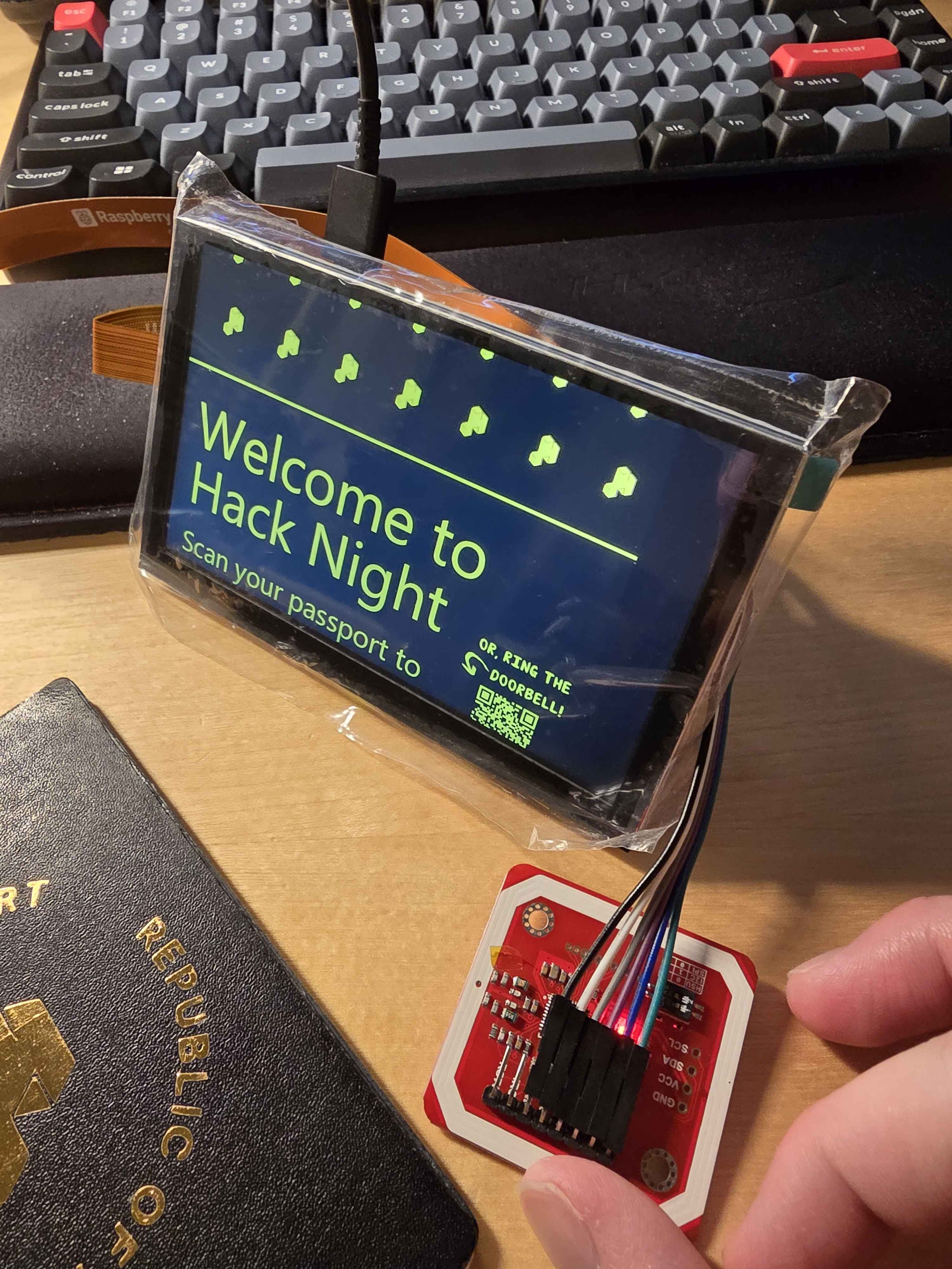
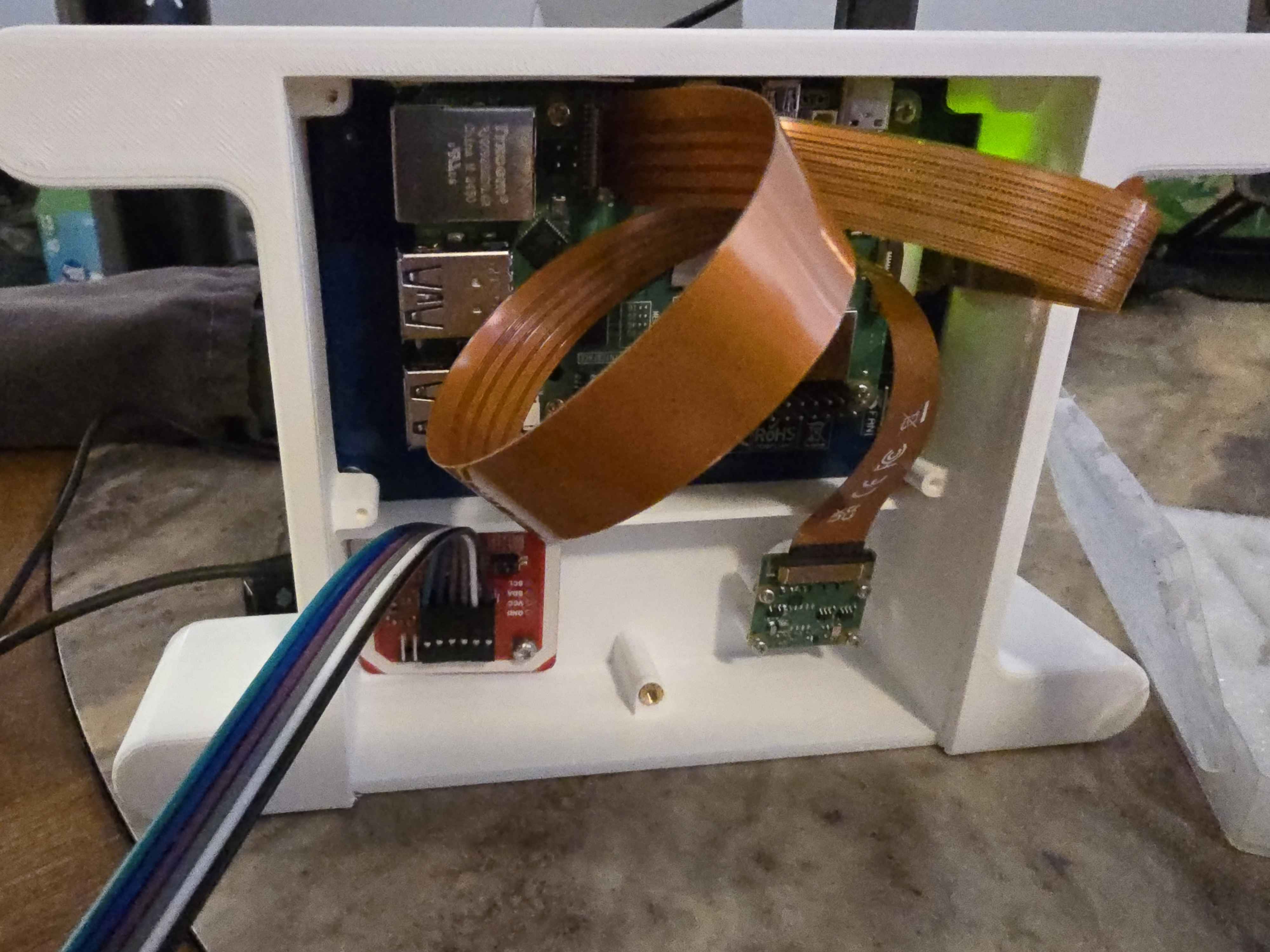
At the end of November, once all the parts had arrived from online marketplaces, I quickly connected together the loose parts on my desk and loaded up the same build from revision one. The visuals were messed up, as expected, but at least we had somewhere to start from!
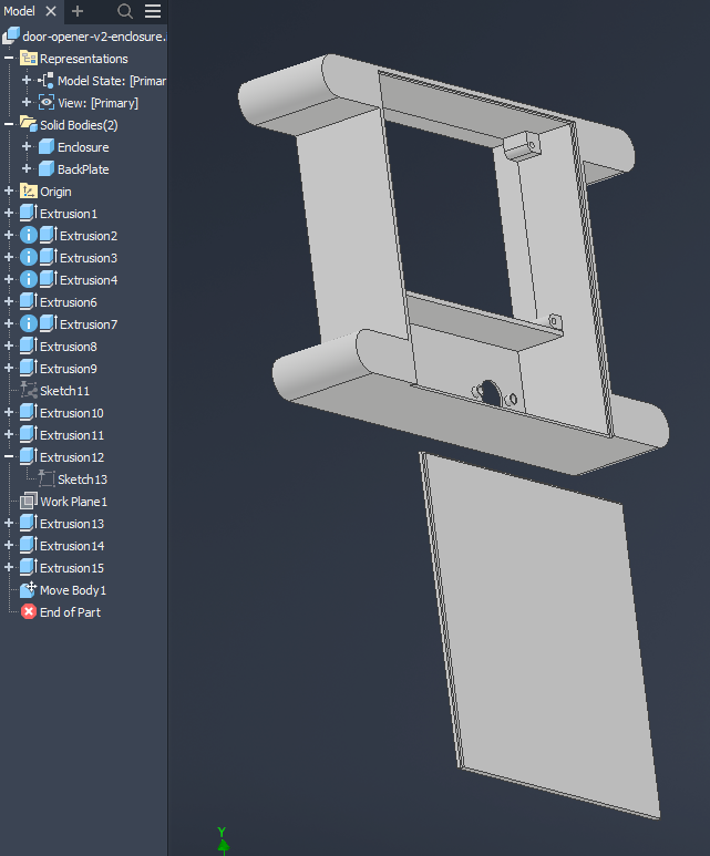
And since I had all the parts sitting in front of me, I took out the calipers and started to take measurements. After sketching out a rough idea of what I wanted, I opened Autodesk Inventor for the first time and made a rudimentary enclosure that would hold the parts together like a test bench:
And that wrapped up Fall 2025, and the rest of the semester was quite busy. After winter break, things picked back up again during the Spring 2026 semester.
What do we name the thing that pushes the ADA button? Some sort of ADA pusher?
Several things happened in parallel as we raced to get this project complete. We finally had the proper linear actuator that had the specifications we needed, shipped all the way from China. It needed 12V of power to operate, and we had an ESP32 board to interface via BLE and send signals to the linear actuator.
At first, I thought that I would only need one USB-PD trigger board and one step-down converter, to change the voltage from 12V to 5V for the ESP32. The trigger board would negotiate 12V from the power source and cleanly power everything.
Unfortunately, if you are familiar with the USB consortium, they actually made the 12V Power Delivery profile optional, which meant a lot of chargers flat-out do not support it. The justification was lack of use: phones usually topped up at around 9V, while laptops and tablets usually went up to 15V and 20V. Thus, the 9V profile was out of the question, even though it would’ve been perfect for our use case.
We couldn’t rely on specific chargers supporting it, because there was a chance that the charger we were using broke and the replacement wouldn’t have the optional profile. And if the charger didn’t support it, rather than risk frying the downstream device, the negotiation automatically shifted down to the next lower voltage profile, which was either 9V or 5V.
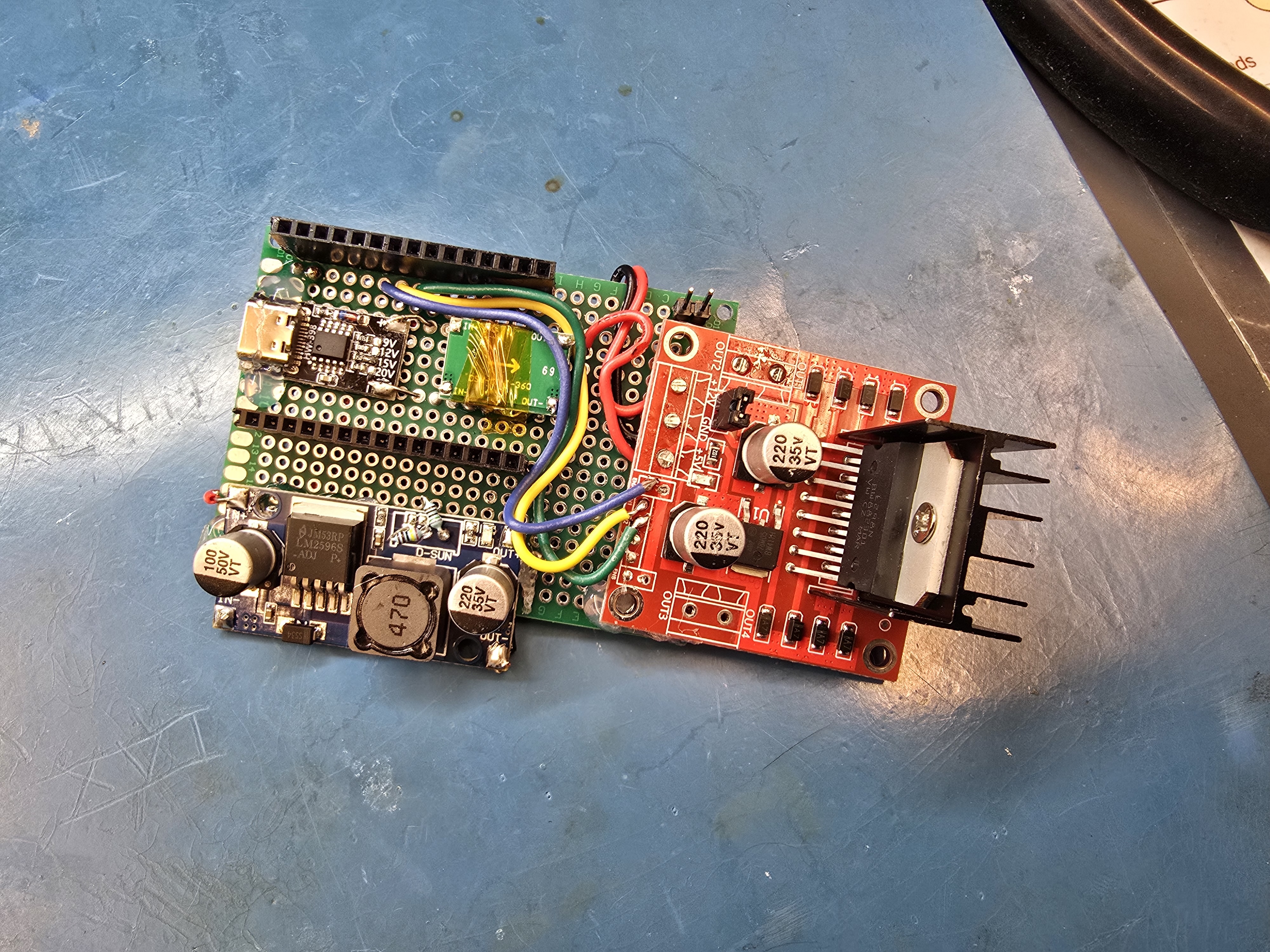
Thus, the new plan was to use two step-down converters and bring the 15V voltage negotiated by the trigger board down, to 12V and 5V, respectively.
After waiting a couple more days for all the parts to arrive, the first
prototype of ada-pusher also materialized on the dining table:
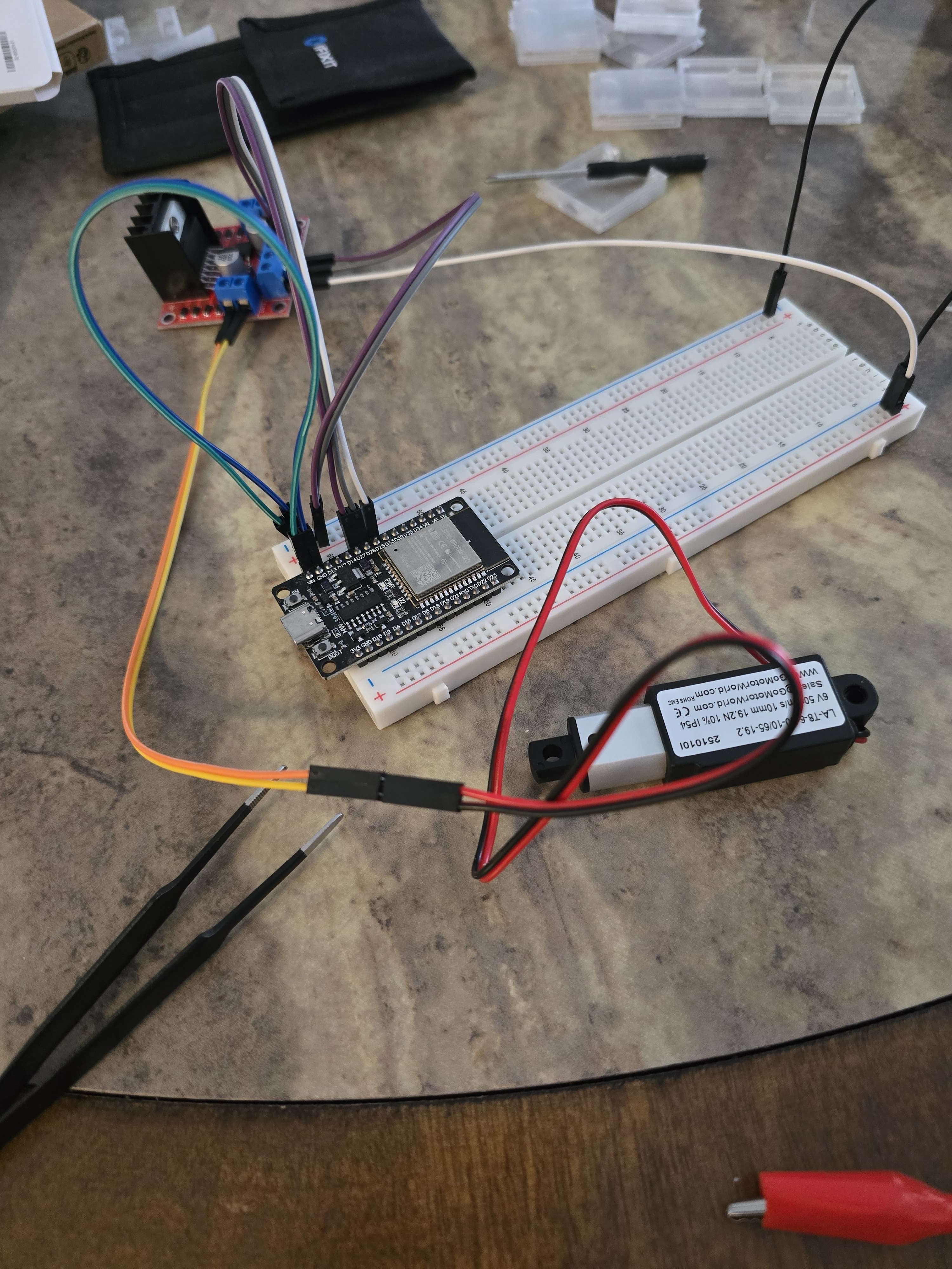
Through this test, we confirmed that the linear actuator module worked, and that the ESP32 board could properly send the signals when prompted.
Then came the topic of mounting the ada-pusher. We came up with several design
ideas, including utilizing the wall panel gaps just above the ada-pusher:
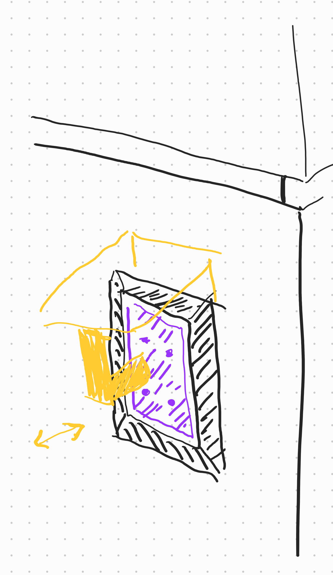
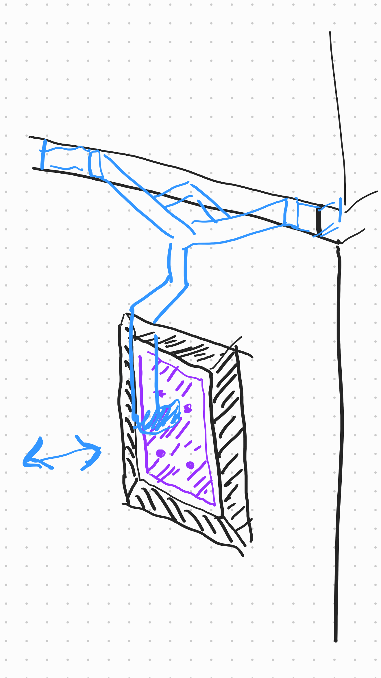
Ultimately, we decided not to move forward with these designs. For the first design, the plastic perimeter around the button was thin and brittle, and we were worried that the contraption hanging off of it could snap it. For the second one, the work to model it in 3D was honestly intimidating to me, as I didn’t have that much experience with CAD software.
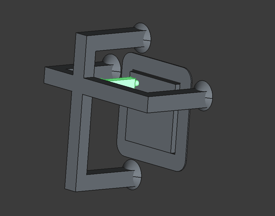
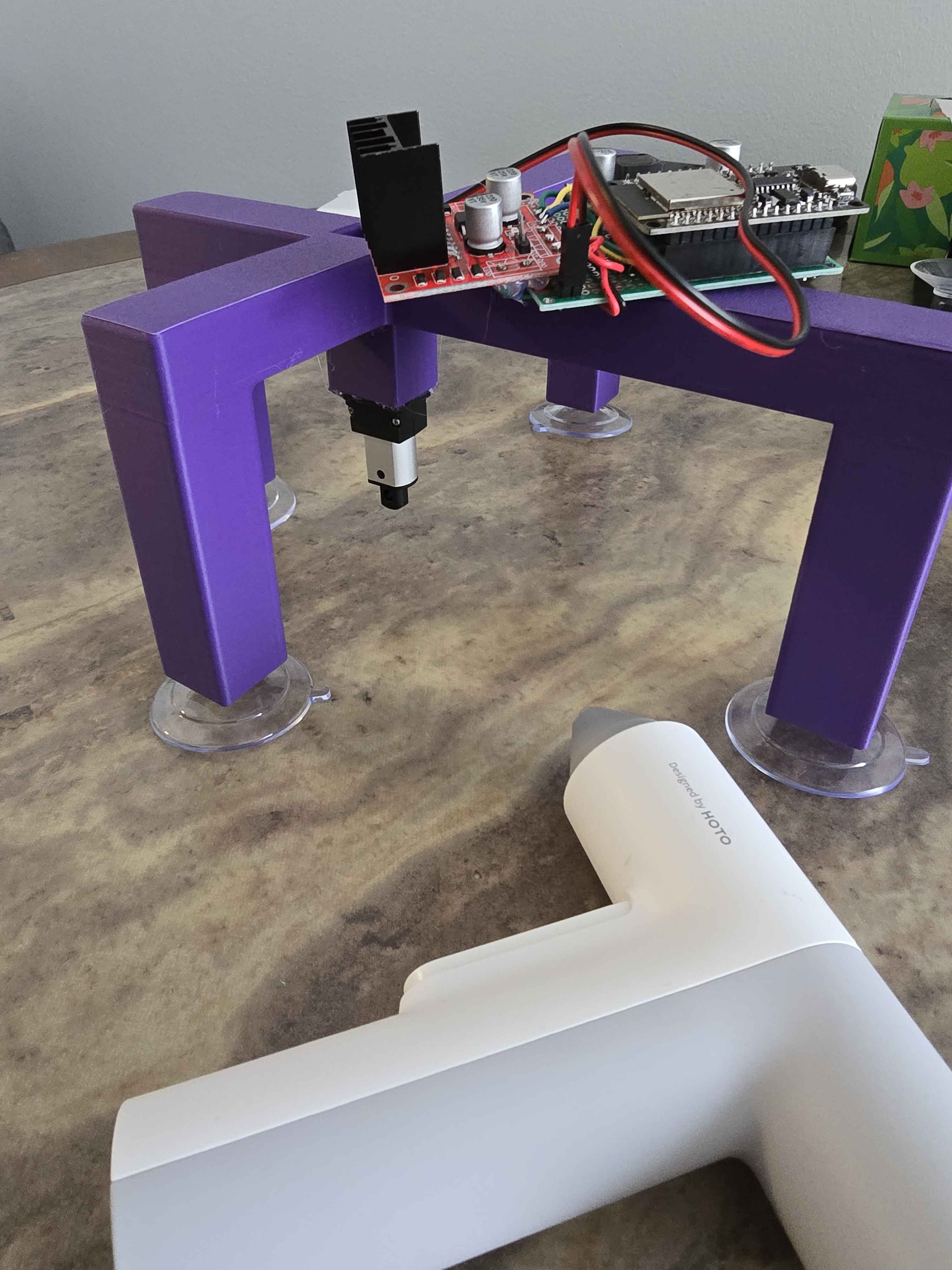
So the lazy but surprisingly effective (?) solution: the original had two suction cups. What if we have four of them?
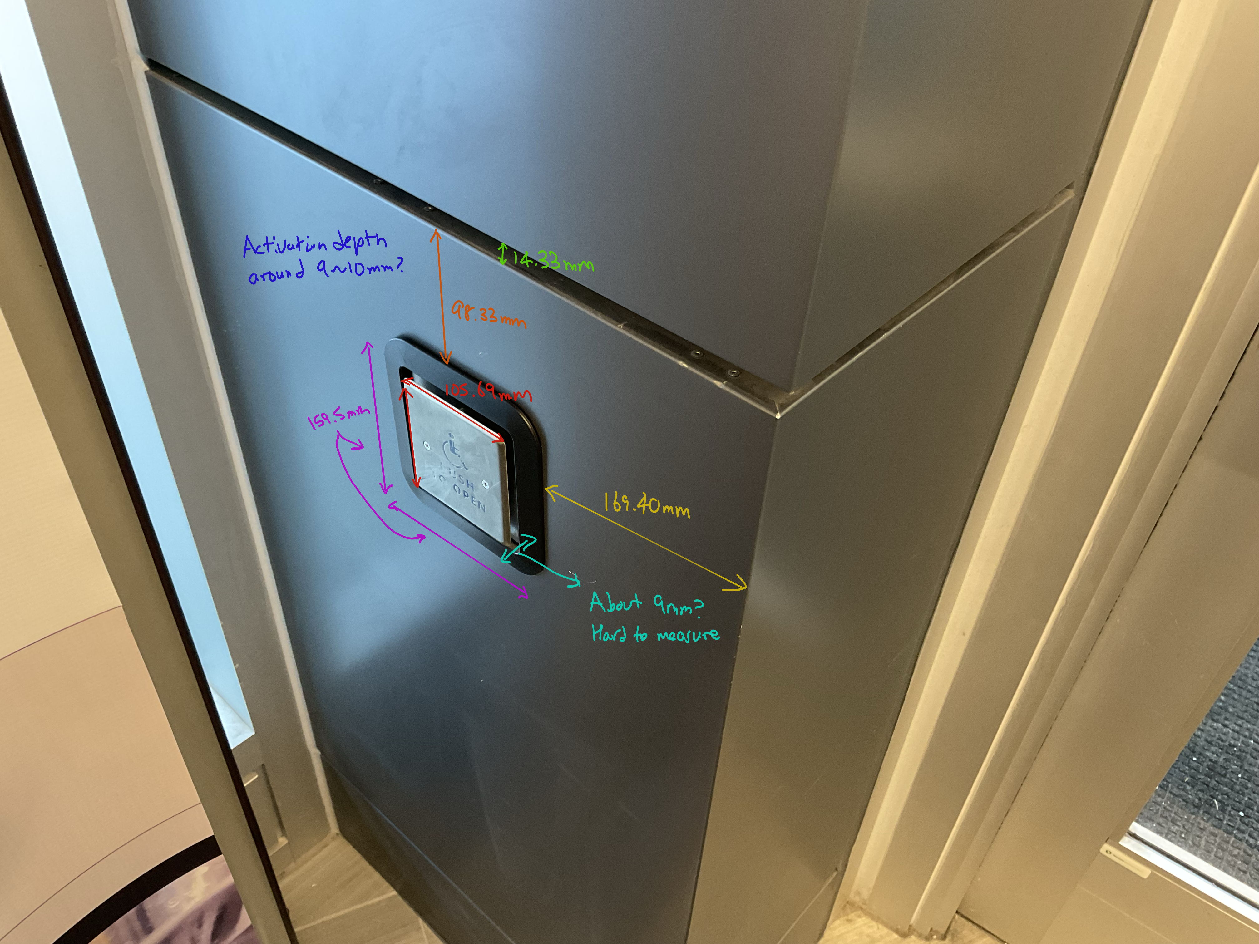
But before we could even start designing how that would look like, we first had to measure the distances and the dimensions of the actual ADA button. So I went on over to Bechtel with my calipers and spent half an hour measuring it.
Since I had such a terrible time dealing with Autodesk licensing at this point, I switched on over to FreeCAD, which worked just as well, given that my project was simple in scale.
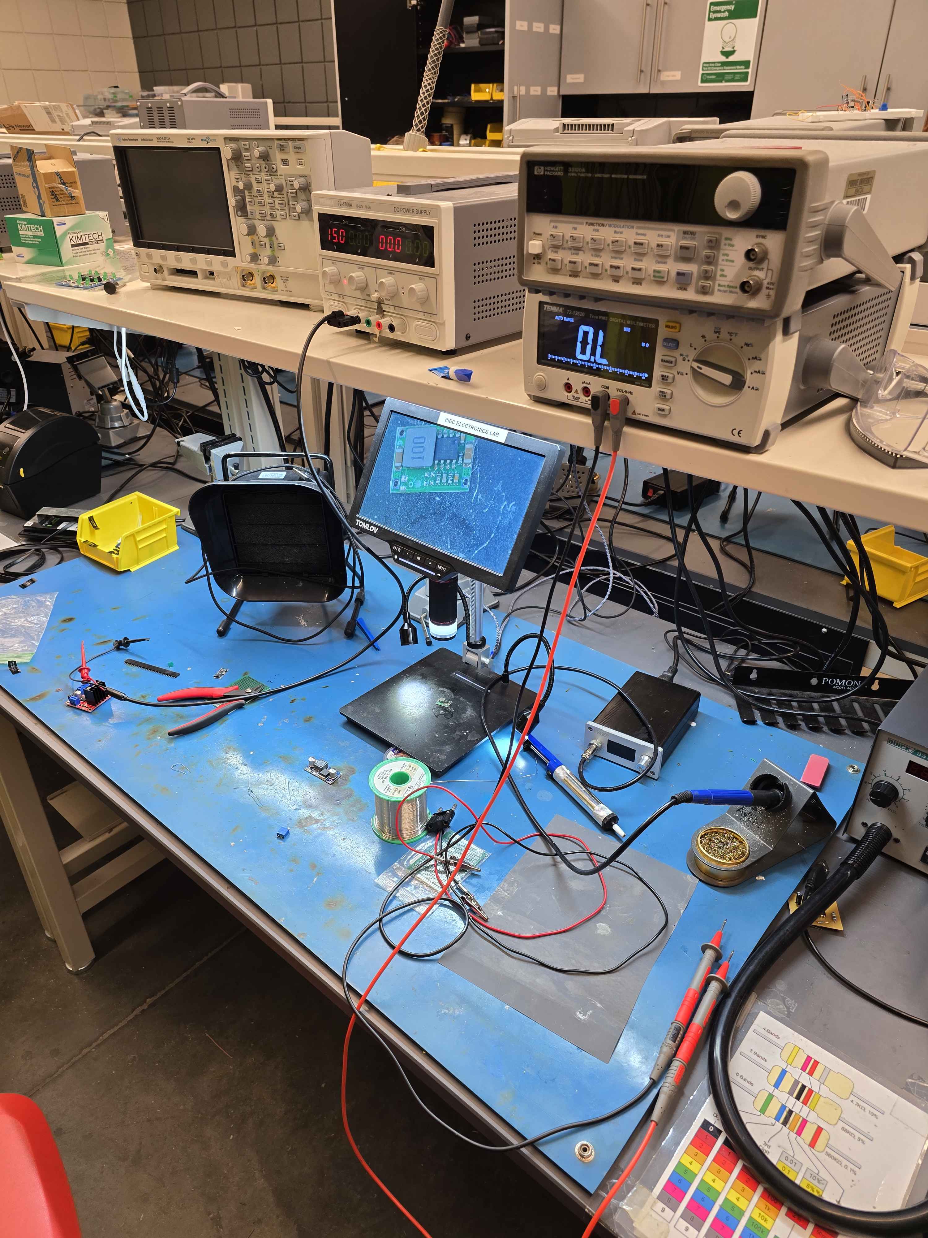
For the electronics part, Bechtel had an electronics lab with good soldering
equipment. However, the circuit for ada-pusher required two step-downs and a
big driver board for the linear actuator, and since we didn’t have time for a
custom PCB, everything was hastily put together on a perfboard.
Meanwhile, on the software side, everything was written atop Rust. The ESP32
platform had good enough support for Rust, although you did have to install a
custom toolchain for Xtensa-based boards, which was what I was using. But the
nimble crate made BLE connections quite easy, and before long I had a working
contraption sitting on my desk!
On the door-opener side, the btleplug crate (yes, it really is named that)
reached out to ada-pusher whenever someone tapped their valid passport. Once
the integration tests worked, the entire caboodle was put in for real-world
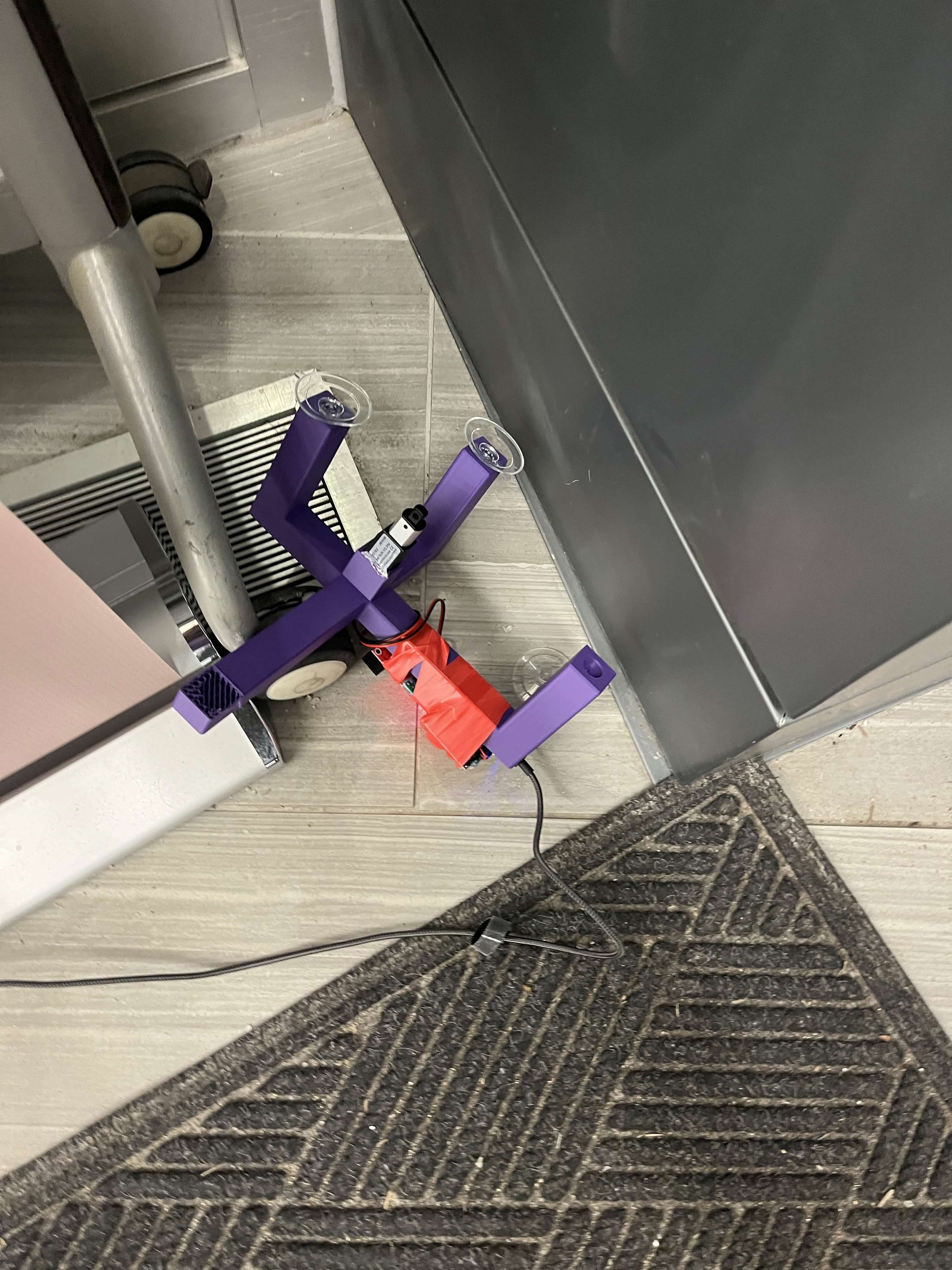
testing at Hack Night 6.18.
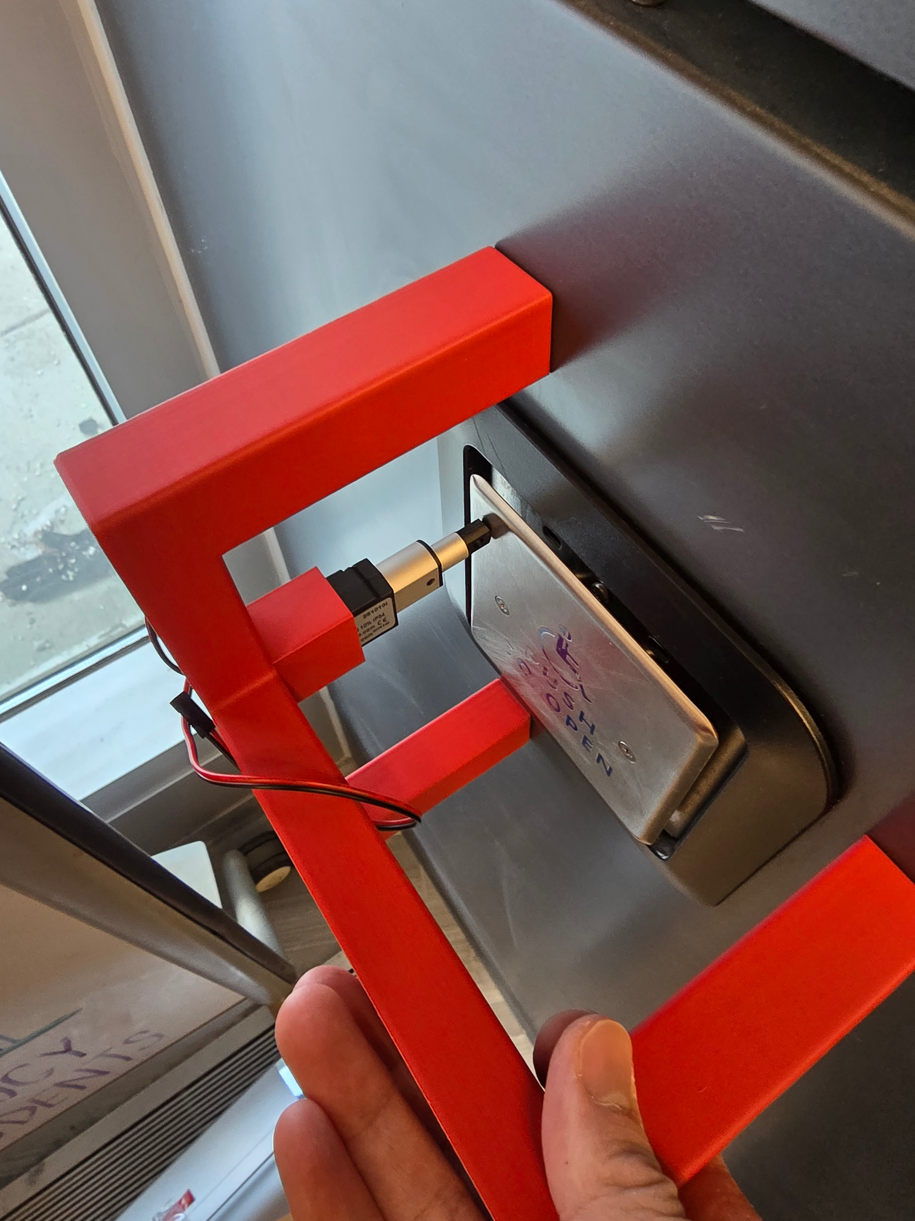
Unfortunately, after an hour or two, someone sent us a photo of the mount failing. Adding insult to injury, because I forgot to put in fillets, one of the legs cleanly sheared off:
Thankfully, adding the fillets was enough to give the next print structural
integrity, and with that, the ada-pusher spinoff project was complete!
Back to the new door-opener
My focus went back to completing door-opener-v2, which also required its fair
share of revisions to the CAD. Even though Purdue has plenty of 3D printers
scattered around campus, trying to find one that isn’t in use was difficult.
At some point, Bechtel’s printers were constantly in use, so I had to go over
to the 3D Printing Club and use their printers to print and test the final few
revisions.
Most of the revisions had to do with tolerances. 3D prints expand on a heated bed and shrink when cool down. 3D printers have different tolerances and prints differ from one another, even with the same Gcode. This made it difficult to tune in the dimensions exactly, such that all the parts fit together with the screws tightly holding them together.
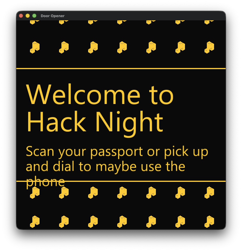
Meanwhile, the software also needed some patches. Besides integrating with
ada-pusher, it had to be adapted to work with the new LCD module of
door-opener-v2. The first revision had hardcoded values for the square LCD
module, which meant that elements were either stretched out, squashed in, or
even off-screen entirely on the new rectangular display.
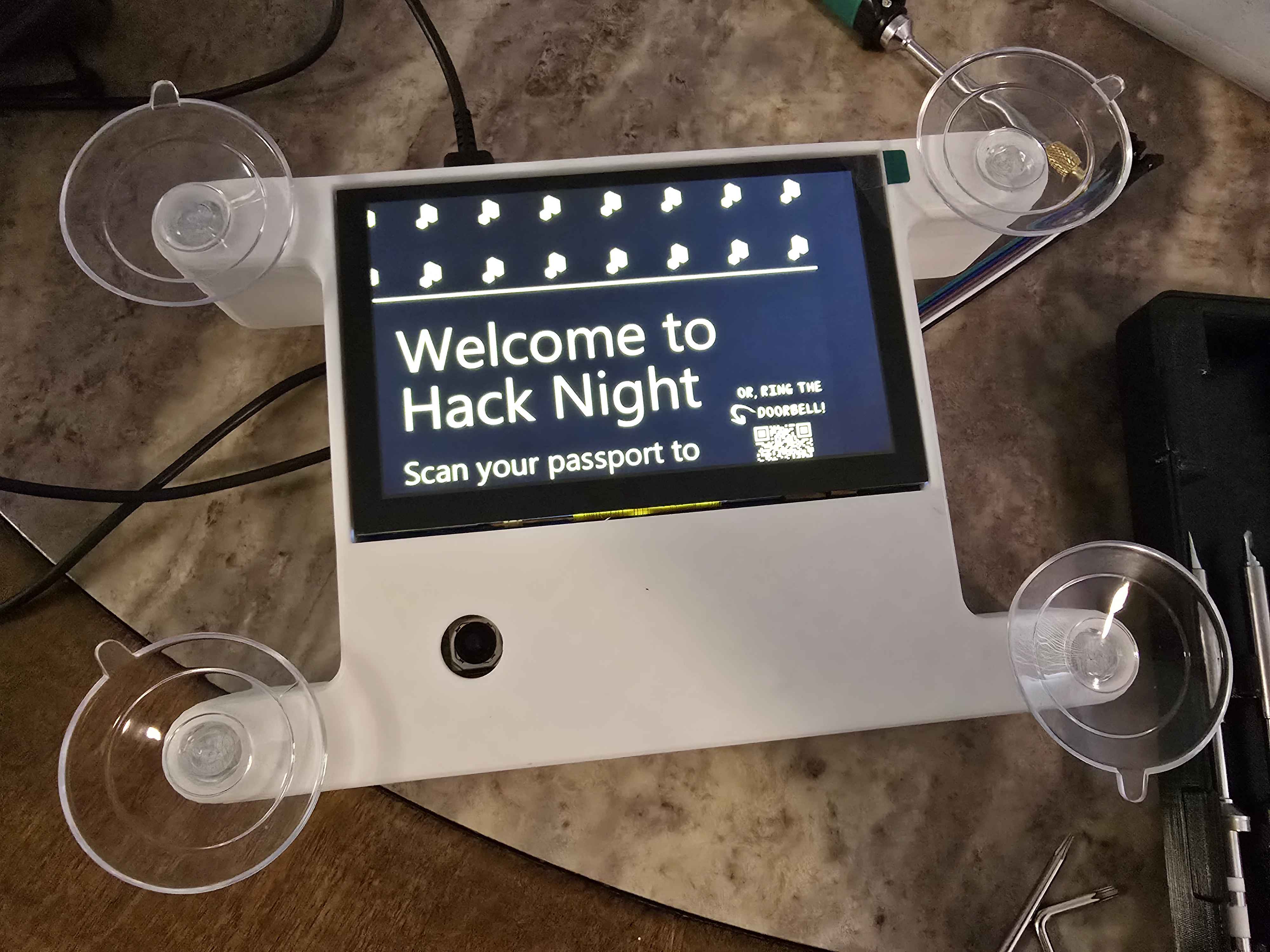
But after the design revisions and the software patches, door-opener-v2 was
finally completed in April and put into service at Hack Night 6.25. For context,
we cut it so close that the Hack Night in question was one day before the
BENTO talk.
The software saw a ton of improvements and new features, which were shown off at BENTO, but here are some of the major ones again:
- Auto-updater for updating the
door-openerapp on boot - Builds moving from the slow Pi to GitHub Actions runners
- Integration with
ada-pusher - Websocket support, which enabled…
- Opening the door using
phone-bell - Opening the door using Discord commands (this was the remote control functionality)
- Opening the door using
- Robust connectivity and health checks and improved user-facing error messages
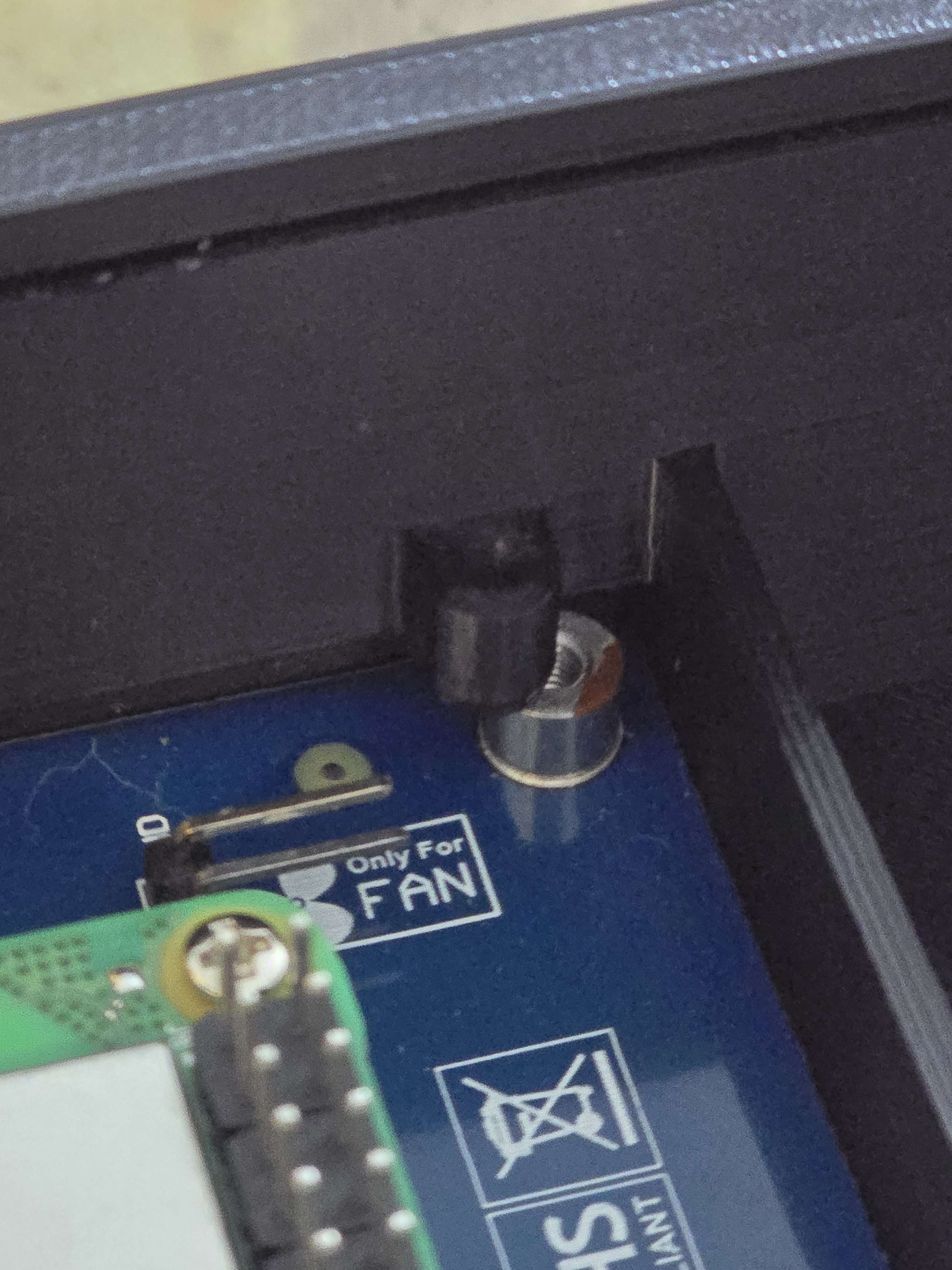
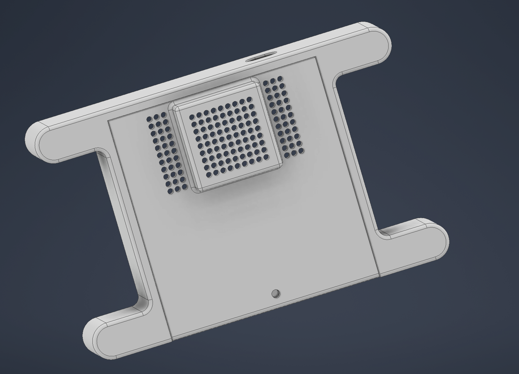
After BENTO, one last modification was required when we realized that the Pi and power circuit was overheating. Thus, the back plate was modified for a small 40 mm fan to sit in:
And on the software side, one feature that unfortunately didn’t make it in time
for testing was the camera module. The idea was that organizers could take a
photo through the camera to see who was in front of the door, then issue the
door open command remotely. Most of the client-side code was implemented
relatively quickly thanks to the nokhwa crate, but the semester ended before
we could start working on the server-side and integration testing.
Retrospective and the future
So that was, in a way, two hardware projects in a trenchcoat. I’m quite happy with the results and the improvements made to the original revision, and the valuable lessons learned working on physical hardware.
With the documentation on the
door-opener repository, anybody should be able to
contribute and add new features to door-opener. That’s exactly how I got
started with Purdue Hackers back in 2024, contributing patches to things that
I found each Hack Night while having a great time with the community. Hopefully,
you’ll see door-opener when you visit one of our Hack Nights and think of
something fun, silly, or cool to add to it!
Also, many thanks to the other organizers and various community members in
helping with the new revision of door-opener! I’m quite hopeful and excited
to see where the project goes next semester.